DynagenでCCIEを目指す
Link Fragmentation and Interleaving (LFI)
最終更新:
it_certification
-
view
1. 目的
- Link Fragmentation and Interleavingの設定について確認します。
2. 構成
2.1. 設定概要
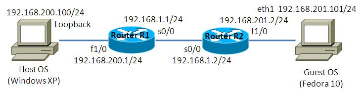
- Host OS側でApacheを起動させます。
- R1, R2間はframe-relayで接続します。
- R1, R2はOSPFでルーティングします。
2.2. 構成図
2.3. netファイル
model = 3620

[localhost]

    [[3620]]
        image = C:\Program Files\Dynamips\images\c3620-j1s3-mz.123-18.bin
        ram = 128

    [[ROUTER R1]]
 		 f1/0 = NIO_gen_eth:\Device\NPF_{8B89D910-5ED3-4A43-9DE9-6A272A3D7592}
        s0/0 = SW 0

    [[FRSW SW]]
        0:100 = 1:100

    [[ROUTER R2]]
		 f1/0 = NIO_gen_eth:\Device\NPF_{5933302A-7AAA-475C-A8FE-A6B82B0C0F98}
        s0/0 = SW 1
2.4. 初期設定
- R1
!
version 12.3
service timestamps debug datetime msec
service timestamps log datetime msec
no service password-encryption
!
hostname R1
!
boot-start-marker
boot-end-marker
!
!
no aaa new-model
ip subnet-zero
!
!
!
ip cef
!
!
!
!
!
!
!
!
!
!
!
!
!
!
!
interface Serial0/0
 ip address 192.168.1.1 255.255.255.0
 encapsulation frame-relay
 ip ospf network broadcast
 serial restart-delay 0
 frame-relay map ip 192.168.1.2 100 broadcast
!
interface Serial0/1
 no ip address
 shutdown
 serial restart-delay 0
!
interface Serial0/2
 no ip address
 shutdown
 serial restart-delay 0
!
interface Serial0/3
 no ip address
 shutdown
 serial restart-delay 0
!
interface FastEthernet1/0
 ip address 192.168.200.1 255.255.255.0
 duplex auto
 speed auto
!
router ospf 1
 log-adjacency-changes
 passive-interface default
 no passive-interface Serial0/0
 network 192.168.1.1 0.0.0.0 area 0
 network 192.168.200.1 0.0.0.0 area 0
!
ip http server
ip classless
!
!
!
!
!
!
!
!
line con 0
line aux 0
line vty 0 4
!
!
end
- R2
!
version 12.3
service timestamps debug datetime msec
service timestamps log datetime msec
no service password-encryption
!
hostname R2
!
boot-start-marker
boot-end-marker
!
!
no aaa new-model
ip subnet-zero
!
!
!
ip cef
!
!
!
!
!
!
!
!
!
!
!
!
!
!
!
interface Serial0/0
 ip address 192.168.1.2 255.255.255.0
 encapsulation frame-relay
 ip ospf network broadcast
 serial restart-delay 0
 frame-relay map ip 192.168.1.1 100 broadcast
!
interface Serial0/1
 no ip address
 shutdown
 serial restart-delay 0
!
interface Serial0/2
 no ip address
 shutdown
 serial restart-delay 0
!
interface Serial0/3
 no ip address
 shutdown
 serial restart-delay 0
!
interface FastEthernet1/0
 ip address 192.168.201.2 255.255.255.0
 duplex auto
 speed auto
!
router ospf 1
 log-adjacency-changes
 passive-interface default
 no passive-interface Serial0/0
 network 192.168.1.2 0.0.0.0 area 0
 network 192.168.201.2 0.0.0.0 area 0
!
ip http server
ip classless
!
!
!
!
!
!
!
!
line con 0
line aux 0
line vty 0 4
!
!
end
2.5. サーバ側 ルーティング設定
- Host OS
route add 192.168.201.0 mask 255.255.255.0 192.168.200.1
- Guest OS
route add -net 192.168.200.0/24 gw 192.168.201.2
3. [検証] I/Fに対する設定
3.1. 設定投入
R1 s0/0でフラグメントを発生される設定を投入します。
R1(config)#interface Serial 0/0
R1(config-if)#frame-relay fragment 500 end-to-end
3.2. 設定確認
show frame-relay fragmentコマンドで設定を確認する事ができます。
R1#show frame-relay fragment
interface                dlci frag-type  size in-frag    out-frag   dropped-frag
Se0/0                    100  end-to-end 500  0          105        0
R1#
4. [検証] map-classを使用した設定
4.1. 設定投入
map-classを用いて、fragmentを定義する事もできます。設定例は以下の通りです。
R1(config)#interface Serial 0/0
R1(config-if)#no frame-relay fragment 500 end-to-end
R1(config-if)#exit
R1(config)#
R1(config)#
R1(config)#map-class frame-relay MAP_FR
R1(config-map-class)#frame-relay traffic-rate 10000000 20000000
R1(config-map-class)#frame-relay fragment 500
R1(config-map-class)#exit
R1(config)#
R1(config)#interface Serial 0/0
R1(config-if)#frame-relay traffic-shaping
R1(config-if)#frame-relay class MAP_FR
R1(config-if)#^Z
4.2. 設定確認
設定確認方法は不明です。判明次第、記事を修正します。
添付ファイル
