DynagenでCCIEを目指す
20100401 rip v1 seconday addressの利用
最終更新:
it_certification
-
view
目的
- classful routing protocolの場合、classfulネットワークの境界で自動集約されてしまい、思うようにルーティングできない事があります。
- そのような場合の対処法として、secondary addressを用いてclassfulネットワークの境界を解消する方法を確かめます。
構成
- 設定概要
- RIPv1でルーティングします。
- 構成図
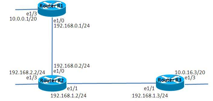
- netファイル
ghostios = True
sparsemem = True
model = 3620
[localhost]

	[[3620]]
		image = C:\Program Files\Dynamips\images\c3620-j1s3-mz.123-18.bin
		ram = 256

	[[ROUTER R1]]
		e1/0 = R2 e1/0

	[[ROUTER R2]]
		e1/1 = R3 e1/1

	[[ROUTER R3]]
- R1
!
version 12.3
service timestamps debug datetime msec
service timestamps log datetime msec
no service password-encryption
!
hostname R1
!
boot-start-marker
boot-end-marker
!
!
no aaa new-model
ip subnet-zero
!
!
!
ip cef
!
!
!
!
!
!
!
!
!
!
!
!
!
!
!
interface Ethernet1/0
 ip address 192.168.0.1 255.255.255.0
 full-duplex
!
interface Ethernet1/1
 no ip address
 shutdown
 half-duplex
!
interface Ethernet1/2
 no ip address
 shutdown
 half-duplex
!
interface Ethernet1/3
 ip address 10.0.0.1 255.255.240.0
 full-duplex
 no keepalive
!
router rip
 network 10.0.0.0
 network 192.168.0.0
!
ip http server
ip classless
!
!
!
!
!
!
!
!
line con 0
line aux 0
line vty 0 4
!
!
end
- R2
!
version 12.3
service timestamps debug datetime msec
service timestamps log datetime msec
no service password-encryption
!
hostname R2
!
boot-start-marker
boot-end-marker
!
!
no aaa new-model
ip subnet-zero
!
!
!
ip cef
!
!
!
!
!
!
!
!
!
!
!
!
!
!
!
interface Ethernet1/0
 ip address 192.168.0.2 255.255.255.0
 full-duplex
!
interface Ethernet1/1
 ip address 192.168.1.2 255.255.255.0
 full-duplex
!
interface Ethernet1/2
 no ip address
 shutdown
 half-duplex
!
interface Ethernet1/3
 ip address 192.168.2.2 255.255.255.0
 full-duplex
 no keepalive
!
router rip
 network 192.168.0.0
 network 192.168.1.0
 network 192.168.2.0
!
ip http server
ip classless
!
!
!
!
!
!
!
!
line con 0
line aux 0
line vty 0 4
!
!
end
- R3
!
version 12.3
service timestamps debug datetime msec
service timestamps log datetime msec
no service password-encryption
!
hostname R3
!
boot-start-marker
boot-end-marker
!
!
no aaa new-model
ip subnet-zero
!
!
!
ip cef
!
!
!
!
!
!
!
!
!
!
!
!
!
!
!
interface Ethernet1/0
 no ip address
 shutdown
 half-duplex
!
interface Ethernet1/1
 ip address 192.168.1.3 255.255.255.0
 full-duplex
!
interface Ethernet1/2
 no ip address
 shutdown
 half-duplex
!
interface Ethernet1/3
 ip address 10.0.16.3 255.255.240.0
 full-duplex
 no keepalive
!
router rip
 network 10.0.0.0
 network 192.168.1.0
!
ip http server
ip classless
!
!
!
!
!
!
!
!
line con 0
line aux 0
line vty 0 4
!
!
end
検証1 経路集約の確認
- ルーティングテーブルの確認
各ルータのルーティングテーブルを確認します。10.0.0.0/20と10.0.16.0/20が10.0.0.0/8に集約されて通知されている事が読み取れます。
R1#show ip route
 - 略 -
     10.0.0.0/20 is subnetted, 1 subnets
C       10.0.0.0 is directly connected, Ethernet1/3
C    192.168.0.0/24 is directly connected, Ethernet1/0
R    192.168.1.0/24 [120/1] via 192.168.0.2, 00:00:00, Ethernet1/0
R    192.168.2.0/24 [120/1] via 192.168.0.2, 00:00:00, Ethernet1/0

R2#show ip route
 - 略 -
R    10.0.0.0/8 [120/1] via 192.168.0.1, 00:00:21, Ethernet1/0
                [120/1] via 192.168.1.3, 00:00:08, Ethernet1/1
C    192.168.0.0/24 is directly connected, Ethernet1/0
C    192.168.1.0/24 is directly connected, Ethernet1/1
C    192.168.2.0/24 is directly connected, Ethernet1/3

R3#show ip route
 - 略 -
     10.0.0.0/20 is subnetted, 1 subnets
C       10.0.16.0 is directly connected, Ethernet1/3
R    192.168.0.0/24 [120/1] via 192.168.1.2, 00:00:15, Ethernet1/1
C    192.168.1.0/24 is directly connected, Ethernet1/1
R    192.168.2.0/24 [120/1] via 192.168.1.2, 00:00:15, Ethernet1/1
- 疎通確認
R1 e1/3とR3 e1/3は互いに疎通不能である事を確認します。
R1#ping 10.0.16.3

Type escape sequence to abort.
Sending 5, 100-byte ICMP Echos to 10.0.16.3, timeout is 2 seconds:
.....
Success rate is 0 percent (0/5)

R3#ping 10.0.0.1

Type escape sequence to abort.
Sending 5, 100-byte ICMP Echos to 10.0.0.1, timeout is 2 seconds:
.....
Success rate is 0 percent (0/5)
検証2 secondary addressの設定
- secondary addressの設定
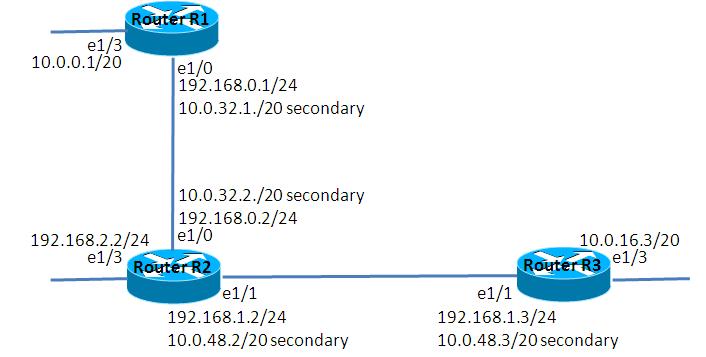
以下の通り、seconday addressを設定します。
R1(config)#interface Ethernet 1/0
R1(config-if)#ip address 10.0.32.1 255.255.240.0 secondary

R2(config)#interface Ethernet 1/0
R2(config-if)#ip address 10.0.32.2 255.255.240.0 secondary
R2(config-if)#exit
R2(config)#interface Ethernet 1/1
R2(config-if)#ip address 10.0.48.2 255.255.240.0 secondary

R3(config)#interface Ethernet 1/1
R3(config-if)#ip address 10.0.48.3 255.255.240.0 secondary
R2のripの設定を修正します。
R2(config)#router rip
R2(config-router)#network 10.0.0.0
以上の結果、できあがった構成は以下の通りです。
- 疎通確認
R1 e1/3とR3 e1/3は互いに疎通可能になった事を確認します。
R1#ping 10.0.16.3

Type escape sequence to abort.
Sending 5, 100-byte ICMP Echos to 10.0.16.3, timeout is 2 seconds:
!!!!!
Success rate is 100 percent (5/5), round-trip min/avg/max = 76/104/148 ms

R3#ping 10.0.0.1

Type escape sequence to abort.
Sending 5, 100-byte ICMP Echos to 10.0.0.1, timeout is 2 seconds:
!!!!!
Success rate is 100 percent (5/5), round-trip min/avg/max = 48/129/216 ms
- ルーティングテーブルの確認
ルーティングテーブルを見ると、R2がやや不可思議な表示になっています。10.0.0.0/20のnext-hopにR1とR3が表示されています。
R1#show ip route
 - 略 -
     10.0.0.0/20 is subnetted, 4 subnets
C       10.0.0.0 is directly connected, Ethernet1/3
R       10.0.16.0 [120/2] via 10.0.32.2, 00:00:15, Ethernet1/0
C       10.0.32.0 is directly connected, Ethernet1/0
R       10.0.48.0 [120/1] via 10.0.32.2, 00:00:15, Ethernet1/0
C    192.168.0.0/24 is directly connected, Ethernet1/0
R    192.168.1.0/24 [120/1] via 192.168.0.2, 00:00:15, Ethernet1/0
                    [120/1] via 10.0.32.2, 00:00:15, Ethernet1/0
R    192.168.2.0/24 [120/1] via 192.168.0.2, 00:00:15, Ethernet1/0
                    [120/1] via 10.0.32.2, 00:00:15, Ethernet1/0
R2#show ip route
 - 略 -
     10.0.0.0/20 is subnetted, 4 subnets
R       10.0.0.0 [120/1] via 192.168.0.1, 00:00:17, Ethernet1/0
                 [120/1] via 192.168.1.3, 00:00:21, Ethernet1/1 <- next-hopがR3
                 [120/1] via 10.0.32.1, 00:00:17, Ethernet1/0
R       10.0.16.0 [120/1] via 10.0.48.3, 00:00:21, Ethernet1/1
C       10.0.32.0 is directly connected, Ethernet1/0
C       10.0.48.0 is directly connected, Ethernet1/1
C    192.168.0.0/24 is directly connected, Ethernet1/0
C    192.168.1.0/24 is directly connected, Ethernet1/1
C    192.168.2.0/24 is directly connected, Ethernet1/3

R3#show ip route
 - 略 -
     10.0.0.0/20 is subnetted, 4 subnets
R       10.0.0.0 [120/1] via 192.168.1.2, 00:00:06, Ethernet1/1
C       10.0.16.0 is directly connected, Ethernet1/3
R       10.0.32.0 [120/1] via 10.0.48.2, 00:00:06, Ethernet1/1
C       10.0.48.0 is directly connected, Ethernet1/1
R    192.168.0.0/24 [120/1] via 192.168.1.2, 00:00:06, Ethernet1/1
                    [120/1] via 10.0.48.2, 00:00:07, Ethernet1/1
C    192.168.1.0/24 is directly connected, Ethernet1/1
R    192.168.2.0/24 [120/1] via 192.168.1.2, 00:00:07, Ethernet1/1
                    [120/1] via 10.0.48.2, 00:00:07, Ethernet1/1
- パケットキャプチャの設定
R2 e1/1のパケットキャプチャを有効にします。
=>capture R2 e1/1 cap_R2_11.cap
- キャプチャ結果の確認
R3からR2へのRIPv1 updateを確認します。送信元が10.0.48.3で10.0.16.0を通知するパケットと、送信元が192.168.1.3で集約ルート10.0.0.0を通知するパケットが確認できます。
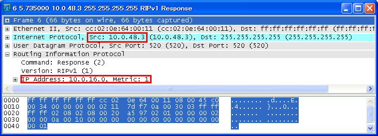
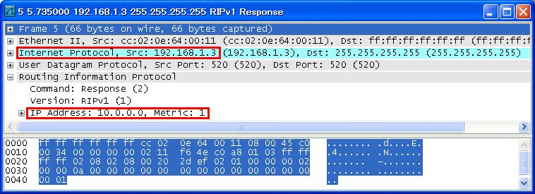
キャプチャの結果から、R2のルーティングテーブルの意味は以下のように解釈する事ができると思います。
R2#show ip route
 - 略 -
     10.0.0.0/20 is subnetted, 4 subnets
R       10.0.0.0 [120/1] via 192.168.0.1, 00:00:17, Ethernet1/0 <- R1からのルート(集約していない)
                 [120/1] via 192.168.1.3, 00:00:21, Ethernet1/1 <- R3からの集約ルート
                 [120/1] via 10.0.32.1, 00:00:17, Ethernet1/0 <- R1からのルート(集約していない)
