DynagenでCCIEを目指す
20100419 OSPF secondary addressの挙動
最終更新:
it_certification
-
view
目的
- OSPF環境下で、secondary addressがどのような挙動をするのかを確かめます。
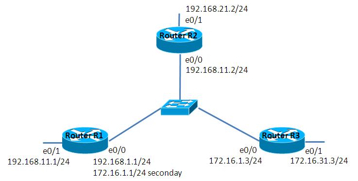
構成
- 設定概要
- OSPFによってルーティングします。
- R1 e0/0にsecondary addressを設定します。
- 構成図
- netファイル
ghostios = True
sparsemem = True
model = 3620
[localhost]

	[[3620]]
		image = C:\Program Files\Dynamips\images\c3620-j1s3-mz.123-18.bin
		ram = 256

	[[ROUTER R1]]
		e0/0 = LAN 1

	[[ROUTER R2]]
		e0/0 = LAN 1

	[[ROUTER R3]]
		e0/0 = LAN 1
- 初期設定 R1
!
version 12.3
service timestamps debug datetime msec
service timestamps log datetime msec
no service password-encryption
!
hostname R1
!
boot-start-marker
boot-end-marker
!
!
no aaa new-model
ip subnet-zero
!
!
!
ip cef
!
!
!
!
!
!
!
!
!
!
!
!
!
!
!
interface Loopback0
 ip address 1.1.1.1 255.255.255.255
!
interface Ethernet0/0
 ip address 172.16.1.1 255.255.255.0 secondary
 ip address 192.168.1.1 255.255.255.0
 full-duplex
!
interface Ethernet0/1
 ip address 192.168.11.1 255.255.255.0
 full-duplex
 no keepalive
!
interface Ethernet0/2
 no ip address
 shutdown
 half-duplex
!
interface Ethernet0/3
 no ip address
 shutdown
 half-duplex
!
router ospf 1
 log-adjacency-changes
 network 192.168.1.0 0.0.0.255 area 0
 network 192.168.11.0 0.0.0.255 area 0
!
ip http server
ip classless
!
!
!
!
!
!
!
!
line con 0
line aux 0
line vty 0 4
!
!
end
- 初期設定 R2
!
version 12.3
service timestamps debug datetime msec
service timestamps log datetime msec
no service password-encryption
!
hostname R2
!
boot-start-marker
boot-end-marker
!
!
no aaa new-model
ip subnet-zero
!
!
!
ip cef
!
!
!
!
!
!
!
!
!
!
!
!
!
!
!
interface Loopback0
 ip address 2.2.2.2 255.255.255.255
!
interface Ethernet0/0
 ip address 192.168.1.2 255.255.255.0
 full-duplex
!
interface Ethernet0/1
 ip address 192.168.21.2 255.255.255.0
 full-duplex
!
interface Ethernet0/2
 no ip address
 shutdown
 half-duplex
!
interface Ethernet0/3
 no ip address
 shutdown
 half-duplex
!
router ospf 1
 log-adjacency-changes
 network 192.168.1.0 0.0.0.255 area 0
 network 192.168.21.0 0.0.0.255 area 0
!
ip http server
ip classless
!
!
!
!
!
!
!
!
line con 0
line aux 0
line vty 0 4
!
!
end
- 初期設定 R3
!
version 12.3
service timestamps debug datetime msec
service timestamps log datetime msec
no service password-encryption
!
hostname R3
!
boot-start-marker
boot-end-marker
!
!
no aaa new-model
ip subnet-zero
!
!
!
ip cef
!
!
!
!
!
!
!
!
!
!
!
!
!
!
!
interface Loopback0
 ip address 3.3.3.3 255.255.255.255
!
interface Ethernet0/0
 ip address 172.16.1.3 255.255.255.0
 full-duplex
!
interface Ethernet0/1
 ip address 172.16.31.3 255.255.255.0
 full-duplex
 no keepalive
!
interface Ethernet0/2
 no ip address
 shutdown
 half-duplex
!
interface Ethernet0/3
 no ip address
 shutdown
 half-duplex
!
router ospf 1
 log-adjacency-changes
 network 172.16.1.0 0.0.0.255 area 0
 network 172.16.31.0 0.0.0.255 area 0
!
ip http server
ip classless
!
!
!
!
!
!
!
!
line con 0
line aux 0
line vty 0 4
!
!
end
検証1 設定の確認
- neighborの確認
ルーティングテーブルとOSPF neighborを表示されます。R1, R3の間でneighborが確立されていない事が確認できます。
R1#show ip route
 - 略 -
     1.0.0.0/32 is subnetted, 1 subnets
C       1.1.1.1 is directly connected, Loopback0
     172.16.0.0/24 is subnetted, 1 subnets
C       172.16.1.0 is directly connected, Ethernet0/0
C    192.168.11.0/24 is directly connected, Ethernet0/1
O    192.168.21.0/24 [110/20] via 192.168.1.2, 00:04:16, Ethernet0/0
C    192.168.1.0/24 is directly connected, Ethernet0/0
R1#show ip ospf neighbor

Neighbor ID     Pri   State           Dead Time   Address         Interface
2.2.2.2           1   FULL/BDR        00:00:37    192.168.1.2     Ethernet0/0
R1#
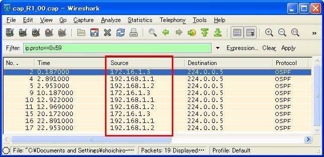
- パケットキャプチャの確認
R1 e0/0にてパケットキャプチャを実施します。R1 e0/0のsecondary address(172.16.1.1)を送信元とするhelloが全く送信されていない事が分かります。この事からsecondary addressを用いてneighborを確立する事ができない事が分かります。(neighborは確立できませんが、secondary addressが属すセグメントをadvertiseする事なら出来ます)
検証2 疎通確認
- 疎通不可の確認
現在の設定ではR3からR2へ疎通できない事を確認します。
R3#ping 192.168.1.2

Type escape sequence to abort.
Sending 5, 100-byte ICMP Echos to 192.168.1.2, timeout is 2 seconds:
.....
Success rate is 0 percent (0/5)
R3#
- staticの定義
R2, R3間で疎通可能となるよう、以下のstaticを定義します。
R2(config)#ip route 0.0.0.0 0.0.0.0 192.168.1.1

R3(config)#ip route 0.0.0.0 0.0.0.0 172.16.1.1
- 疎通確認
R3からR2へ疎通可能である事を確認します。
R3#ping 192.168.1.2

Type escape sequence to abort.
Sending 5, 100-byte ICMP Echos to 192.168.1.2, timeout is 2 seconds:
!!!!!
Success rate is 100 percent (5/5), round-trip min/avg/max = 64/91/140 ms
検証3 RIPの併用
- 設定削除
neighborが確立できないR1, R3間のOSPFの設定を以下の要領で削除します。
R1(config)#router ospf 1
R1(config-router)#no network 172.16.1.0 0.0.0.255 area 0

R3(config)#no router ospf 1
- RIPの併用
RIPはsecondary addressでも経路が交換できるので、RIPを用いてR1, R3間の経路を交換します。また、RIPとOSPFを互いに再配送する事で全ての経路を交換できるようにします。
R1(config)#router rip
R1(config-router)#network 172.16.0.0
R1(config-router)#network 192.168.1.0
R1(config-router)#network 192.168.11.0
R1(config-router)#no auto-summary
R1(config-router)#redistribute ospf 1
R1(config-router)#exit
R1(config)#router ospf 1
R1(config-router)#redistribute rip subnets

R3(config)#router rip
R3(config-router)#network 172.16.0.0
R3(config-router)#no auto-summary
- ルーティングテーブルの確認
R2のルーティングテーブルを確認すると、R3への経路がRIPからOSPFに再配送されて通知された様子が確認できます。
R2#show ip route
Codes: C - connected, S - static, R - RIP, M - mobile, B - BGP
       D - EIGRP, EX - EIGRP external, O - OSPF, IA - OSPF inter area
       N1 - OSPF NSSA external type 1, N2 - OSPF NSSA external type 2
       E1 - OSPF external type 1, E2 - OSPF external type 2
       i - IS-IS, su - IS-IS summary, L1 - IS-IS level-1, L2 - IS-IS level-2
       ia - IS-IS inter area, * - candidate default, U - per-user static route
       o - ODR, P - periodic downloaded static route

Gateway of last resort is 192.168.1.1 to network 0.0.0.0

     2.0.0.0/32 is subnetted, 1 subnets
C       2.2.2.2 is directly connected, Loopback0
     172.16.0.0/24 is subnetted, 2 subnets
O E2    172.16.31.0 [110/20] via 192.168.1.1, 00:07:18, Ethernet0/0 <- R3への経路
O E2    172.16.1.0 [110/20] via 192.168.1.1, 00:07:18, Ethernet0/0  <- R3への経路
O    192.168.11.0/24 [110/20] via 192.168.1.1, 00:07:18, Ethernet0/0
C    192.168.21.0/24 is directly connected, Ethernet0/1
C    192.168.1.0/24 is directly connected, Ethernet0/0
S*   0.0.0.0/0 [1/0] via 192.168.1.1
R2#
補足1 OSPFからRIPへの再配送
- OSPFからRIPへ
R3のルーティングテーブルを確認すると、R2への経路が載っていない事が分かります。OSPFからRIPへの再配送で失敗しているようです。原因が分かり次第加筆したいと思います。
R3#show ip route
Codes: C - connected, S - static, R - RIP, M - mobile, B - BGP
       D - EIGRP, EX - EIGRP external, O - OSPF, IA - OSPF inter area
       N1 - OSPF NSSA external type 1, N2 - OSPF NSSA external type 2
       E1 - OSPF external type 1, E2 - OSPF external type 2
       i - IS-IS, su - IS-IS summary, L1 - IS-IS level-1, L2 - IS-IS level-2
       ia - IS-IS inter area, * - candidate default, U - per-user static route
       o - ODR, P - periodic downloaded static route

Gateway of last resort is 172.16.1.1 to network 0.0.0.0

     3.0.0.0/32 is subnetted, 1 subnets
C       3.3.3.3 is directly connected, Loopback0
     172.16.0.0/24 is subnetted, 2 subnets
C       172.16.31.0 is directly connected, Ethernet0/1
C       172.16.1.0 is directly connected, Ethernet0/0
R    192.168.11.0/24 [120/1] via 172.16.1.1, 00:00:27, Ethernet0/0
S*   0.0.0.0/0 [1/0] via 172.16.1.1
R3#
