DynagenでCCIEを目指す
20100331 rip passive-interfaceの設定
最終更新:
it_certification
-
view
目的
- RIPの経路交換をユニキャストで行う方法を確認します。
構成
- 設定概要
- RIPでルーティングします。
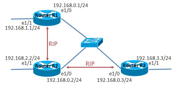
- 構成図
- netファイル
ghostios = True
sparsemem = True
model = 3620
[localhost]

    [[3620]]
        image = C:\Program Files\Dynamips\images\c3620-j1s3-mz.123-18.bin
        ram = 256

    [[ROUTER R1]]
    	e1/0 = LAN 1

    [[ROUTER R2]]
    	e1/0 = LAN 1

    [[ROUTER R3]]
    	e1/0 = LAN 1
- R1
!
version 12.3
service timestamps debug datetime msec
service timestamps log datetime msec
no service password-encryption
!
hostname R1
!
boot-start-marker
boot-end-marker
!
!
no aaa new-model
ip subnet-zero
!
!
!
ip cef
!
!
!
!
!
!
!
!
!
!
!
!
!
!
!
interface Ethernet1/0
 ip address 192.168.0.1 255.255.255.0
 full-duplex
!
interface Ethernet1/1
 ip address 192.168.1.1 255.255.255.0
 full-duplex
 no keepalive
!
interface Ethernet1/2
 no ip address
 shutdown
 half-duplex
!
interface Ethernet1/3
 no ip address
 shutdown
 half-duplex
!
router rip
 version 2
 network 192.168.0.0
 network 192.168.1.0
 no auto-summary
!
ip http server
ip classless
!
!
no cdp run
!
!
!
!
!
!
line con 0
line aux 0
line vty 0 4
!
!
end
- R2
!
version 12.3
service timestamps debug datetime msec
service timestamps log datetime msec
no service password-encryption
!
hostname R2
!
boot-start-marker
boot-end-marker
!
!
no aaa new-model
ip subnet-zero
!
!
!
ip cef
!
!
!
!
!
!
!
!
!
!
!
!
!
!
!
interface Ethernet1/0
 ip address 192.168.0.2 255.255.255.0
 full-duplex
!
interface Ethernet1/1
 ip address 192.168.2.2 255.255.255.0
 half-duplex
 no keepalive
!
interface Ethernet1/2
 no ip address
 shutdown
 half-duplex
!
interface Ethernet1/3
 no ip address
 shutdown
 half-duplex
!
router rip
 version 2
 network 192.168.0.0
 network 192.168.2.0
!
ip http server
ip classless
!
!
no cdp run
!
!
!
!
!
!
line con 0
line aux 0
line vty 0 4
!
!
end
- R3
!
version 12.3
service timestamps debug datetime msec
service timestamps log datetime msec
no service password-encryption
!
hostname R3
!
boot-start-marker
boot-end-marker
!
!
no aaa new-model
ip subnet-zero
!
!
!
ip cef
!
!
!
!
!
!
!
!
!
!
!
!
!
!
!
interface Ethernet1/0
 ip address 192.168.0.3 255.255.255.0
 full-duplex
!
interface Ethernet1/1
 ip address 192.168.3.3 255.255.255.0
 full-duplex
 no keepalive
!
interface Ethernet1/2
 no ip address
 shutdown
 half-duplex
!
interface Ethernet1/3
 no ip address
 shutdown
 half-duplex
!
router rip
 version 2
 network 192.168.0.0
 network 192.168.3.0
!
ip http server
ip classless
!
!
no cdp run
!
!
!
!
!
!
line con 0
line aux 0
line vty 0 4
!
!
end
検証1 multicast updateの確認
- デバッグの有効化
R1で下記デバッグを有効にします。
R1(config)#debug ip rip events
- パケットキャプチャの設定
R2 e1/0に対してパケットキャプチャの設定を行います。
=> capture R2 e1/0 cap_R2_10.cap
- デバッグメッセージの確認
R1がR2とR3の両方と経路を交換している事が読み取れます。また、宛先はマルチキャストアドレスになっています。
*Mar  1 00:29:41.067: RIP: sending v2 update to 224.0.0.9 via Ethernet1/1 (192.168.1.1)
*Mar  1 00:29:41.071: RIP: Update contains 3 routes
*Mar  1 00:29:41.071: RIP: Update queued
*Mar  1 00:29:41.071: RIP: Update sent via Ethernet1/1
*Mar  1 00:29:41.987: RIP: received v2 update from 192.168.0.2 on Ethernet1/0 <- R2に対してupdateを送信
*Mar  1 00:29:41.991: RIP: Update contains 1 routes
*Mar  1 00:29:42.571: RIP: sending v2 update to 224.0.0.9 via Ethernet1/0 (192.168.0.1)
*Mar  1 00:29:42.575: RIP: Update contains 1 routes
*Mar  1 00:29:42.575: RIP: Update queued
*Mar  1 00:29:42.575: RIP: Update sent via Ethernet1/0
*Mar  1 00:29:43.703: RIP: received v2 update from 192.168.0.3 on Ethernet1/0 <- R3に対してupdateを送信
*Mar  1 00:29:43.707: RIP: Update contains 1 routes
*Mar  1 00:30:08.807: RIP: sending v2 update to 224.0.0.9 via Ethernet1/1 (192.168.1.1)
*Mar  1 00:30:08.811: RIP: Update contains 3 routes
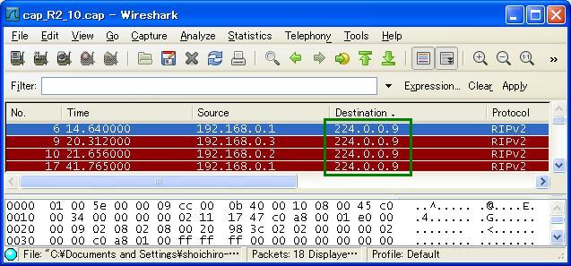
- パケットキャプチャの確認
宛先がマルチキャストアドレスになっている事が確認できます。
検証2 uicast updateの確認
- passive-interfaceの設定
構成図の通りのunicastでRIP情報を交換するように設定します。passive-interfaceを指定すると、neighborコマンドで明示的に指定したルータ以外とは経路を交換しないようになります。
R1に以下の設定を投入します。
R1に以下の設定を投入します。
R1(config)#router rip
R1(config-router)#passive-interface Ethernet 1/0
R1(config-router)#neighbor 192.168.0.2
R3に以下の設定を投入します。
R3(config)#router rip
R3(config-router)#passive-interface Ethernet 1/0
R3(config-router)#neighbor 192.168.0.2
- デバッグの有効化
R1で下記デバッグを有効にします。
R1(config)#debug ip rip events
- パケットキャプチャの設定
R2 e1/0に対してパケットキャプチャの設定を行います。
=> capture R2 e1/0 cap_R2_10.cap
- デバッグメッセージの確認
検証1の時と異なり、R3(192.168.0.3)からのupdateが確認できません。
*Mar  1 00:47:47.791: RIP: Update sent via Ethernet1/0
*Mar  1 00:47:47.791: RIP: Update sent via Ethernet1/1
*Mar  1 00:47:51.379: RIP: sending v2 update to 192.168.0.2 via Ethernet1/0 (192.168.0.1)
*Mar  1 00:47:51.383: RIP: Update contains 2 routes
*Mar  1 00:47:51.383: RIP: Update queued
*Mar  1 00:47:51.387: RIP: Update sent via Ethernet1/0
*Mar  1 00:47:53.335: RIP: sending v2 update to 224.0.0.9 via Ethernet1/1 (192.168.1.1)
*Mar  1 00:47:53.339: RIP: Update contains 3 routes
*Mar  1 00:47:53.339: RIP: Update queued
*Mar  1 00:47:53.339: RIP: Update sent via Ethernet1/1
*Mar  1 00:48:14.043: RIP: received v2 update from 192.168.0.2 on Ethernet1/0
*Mar  1 00:48:14.047: RIP: Update contains 1 routes
*Mar  1 00:48:19.967: RIP: sending v2 update to 192.168.0.2 via Ethernet1/0 (192.168.0.1)
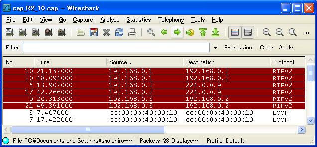
- パケットキャプチャの確認
passive-interfaceが設定されているR1, R3はユニキャストでupdateを送信している事が分かります。また、passiveではないR2はマルチキャストでupdateを送信している事が分かります。
検証3 split-holizon
- ルーティングテーブルの確認
R1とR3で経路を交換できていない事が分かります。
R1#show ip route
C    192.168.0.0/24 is directly connected, Ethernet1/0
C    192.168.1.0/24 is directly connected, Ethernet1/1
R    192.168.2.0/24 [120/1] via 192.168.0.2, 00:00:12, Ethernet1/0

R3#show ip route
 - 略 -
C    192.168.0.0/24 is directly connected, Ethernet1/0
R    192.168.2.0/24 [120/1] via 192.168.0.2, 00:00:02, Ethernet1/0
C    192.168.3.0/24 is directly connected, Ethernet1/1
- split-holizonの無効化
R2 e1/0でsplit-holizonを無効にします。
R2(config)#interface Ethernet 1/0
R2(config-if)#no ip split-horizon
- ルーティングテーブルの再確認
split-holizon無効化によって、R1とR3が経路を交換できるようになった事が確認できます。
R1#show ip route
C    192.168.0.0/24 is directly connected, Ethernet1/0
C    192.168.1.0/24 is directly connected, Ethernet1/1
R    192.168.2.0/24 [120/1] via 192.168.0.2, 00:00:24, Ethernet1/0
R    192.168.3.0/24 [120/2] via 192.168.0.2, 00:00:24, Ethernet1/0 <- R3へのルート

R3#show ip route
C    192.168.0.0/24 is directly connected, Ethernet1/0
R    192.168.1.0/24 [120/2] via 192.168.0.2, 00:00:25, Ethernet1/0 <- R1へのルート
R    192.168.2.0/24 [120/1] via 192.168.0.2, 00:00:25, Ethernet1/0
C    192.168.3.0/24 is directly connected, Ethernet1/1
