DynagenでCCIEを目指す
Frame Relay on multipoint sub Interface
最終更新:
it_certification
-
view
1. 目的
- サブI/F (multipoint) に対するframe-relayの設定方法を確認します。
2. 構成
2.1. 設定概要
- SWをフレームリレースイッチとして代用します。
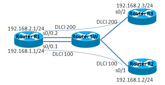
2.2. 構成図
2.3. netファイル
model = 3620

[localhost]

    [[3620]]
        image = C:\Program Files\Dynamips\images\c3620-j1s3-mz.123-18.bin
        ram = 128

    [[ROUTER R1]]
        s0/0 = SW s0/0

    [[ROUTER SW]]
    	s0/1 = R2 s0/1
    	s0/2 = R3 s0/2

    [[ROUTER R2]]

    [[ROUTER R3]]
2.4. 初期設定
- R1
デフォルト設定
- SW1
デフォルト設定
- R2
デフォルト設定
- R3
デフォルト設定
3. [準備] 検証準備
3.1. フレームリレースイッチの作成
SWをフレームリレースイッチとして代用します。SWに投入する設定は以下の通りです。
Router(config)#hostname SW
SW(config)#
SW(config)#frame-relay switching
SW(config)#
SW(config)#interface Serial 0/0
SW(config-if)#encapsulation frame-relay
SW(config-if)#frame-relay lmi-type cisco <- LMIを指定します。デフォルトはciscoですので、ciscoを使用する場合は省略可能です。
SW(config-if)#frame-relay intf-type dce
SW(config-if)#clock rate 6420 <- clock rateを指定します。実機では必須の設定ですが、dynagenなどの仮想環境では設定を省いても疎通可能です。
SW(config-if)#frame-relay route 200 interface Serial 0/1 200
SW(config-if)#frame-relay route 300 interface Serial 0/2 300
SW(config-if)#no shutdown
SW(config-if)#exit
SW(config)#
SW(config)#interface Serial 0/1
SW(config-if)#encapsulation frame-relay
SW(config-if)#frame-relay intf-type dce
SW(config-if)#clock rate 6420
SW(config-if)#frame-relay route 200 interface Serial 0/0 200
SW(config-if)#no shutdown
SW(config-if)#exit
SW(config)#
SW(config)#interface Serial 0/2
SW(config-if)#encapsulation frame-relay
SW(config-if)#frame-relay intf-type dce
SW(config-if)#clock rate 6420
SW(config-if)#frame-relay route 300 interface Serial 0/0 300
SW(config-if)#no shutdown
SW(config-if)#exit
3.2. フレームリレースイッチ ルーティングの確認
SWのルーティングを確認します。
SW#show frame-relay route
Input Intf      Input Dlci      Output Intf     Output Dlci     Status
Serial0/0       200             Serial0/1       200             inactive
Serial0/0       300             Serial0/2       300             inactive
Serial0/1       200             Serial0/0       200             inactive
Serial0/2       300             Serial0/0       300             inactive
SW#
3.3. 物理I/Fの設定
R2, R3の物理I/Fに対して、frame-relayの設定を投入します。
Router(config)#hostname R2
R2(config)#interface Serial 0/1
R2(config-if)#encapsulation frame-relay
R2(config-if)#ip address 192.168.1.2 255.255.255.0
R2(config-if)#no shutdown

Router(config)#hostname R3
R3(config)#interface Serial 0/2
R3(config-if)#encapsulation frame-relay
R3(config-if)#ip address 192.168.1.3 255.255.255.0
R3(config-if)#no shutdown
4. [検証] sub I/Fに対するフレームリレーの設定
4.1. 設定投入
R1, R2のsub I/Fをmultipointとして、フレームリレーの設定を行います。sub I/Fの場合は、LMIによりDLCIを取得できないので、DLCIを明示的に設定する必要があります。
Router(config)#hostname R1
R1(config)#interface Serial 0/0
R1(config-if)#no ip address
R1(config-if)#encapsulation frame-relay
R1(config-if)#no shutdown
R1(config-if)#exit
R1(config)#
R1(config)#
R1(config)#interface Serial 0/0.1 multipoint
R1(config-subif)#ip address 192.168.1.1 255.255.255.0
R1(config-subif)#frame-relay interface-dlci 200
R1(config-fr-dlci)#exit
R1(config-subif)#frame-relay interface-dlci 300
R1(config-fr-dlci)#exit
R1(config-subif)#^Z
R1#
PVCの設定について確認します。
R1#show frame-relay pvc

PVC Statistics for interface Serial0/0 (Frame Relay DTE)

              Active     Inactive      Deleted       Static
  Local          2            0            0            0
  Switched       0            0            0            0
  Unused         0            0            0            0

DLCI = 200, DLCI USAGE = LOCAL, PVC STATUS = ACTIVE, INTERFACE = Serial0/0.1

  input pkts 16            output pkts 0            in bytes 544
  out bytes 0              dropped pkts 0           in pkts dropped 0
  out pkts dropped 0                out bytes dropped 0
  in FECN pkts 0           in BECN pkts 0           out FECN pkts 0
  out BECN pkts 0          in DE pkts 0             out DE pkts 0
  out bcast pkts 0         out bcast bytes 0
  5 minute input rate 0 bits/sec, 0 packets/sec
  5 minute output rate 0 bits/sec, 0 packets/sec
  pvc create time 00:16:20, last time pvc status changed 00:16:10

DLCI = 300, DLCI USAGE = LOCAL, PVC STATUS = ACTIVE, INTERFACE = Serial0/0.1

  input pkts 16            output pkts 0            in bytes 544
  out bytes 0              dropped pkts 0           in pkts dropped 0
  out pkts dropped 0                out bytes dropped 0
  in FECN pkts 0           in BECN pkts 0           out FECN pkts 0
  out BECN pkts 0          in DE pkts 0             out DE pkts 0
  out bcast pkts 0         out bcast bytes 0
  5 minute input rate 0 bits/sec, 0 packets/sec
  5 minute output rate 0 bits/sec, 0 packets/sec
  pvc create time 00:16:21, last time pvc status changed 00:16:11
R1#
DLCIの設定について確認します。
R1#show frame-relay map
Serial0/0.1 (up): ip 192.168.1.2 dlci 200(0xC8,0x3080), dynamic,
              broadcast,, status defined, active
Serial0/0.1 (up): ip 192.168.1.3 dlci 300(0x12C,0x48C0), dynamic,
              broadcast,, status defined, active
R1#
4.2. 疎通確認
R1, R2, R3間で疎通が可能な事を確認します。
R1#ping 192.168.1.2

Type escape sequence to abort.
Sending 5, 100-byte ICMP Echos to 192.168.1.2, timeout is 2 seconds:
!!!!!
Success rate is 100 percent (5/5), round-trip min/avg/max = 12/44/136 ms
R1#ping 192.168.1.3

Type escape sequence to abort.
Sending 5, 100-byte ICMP Echos to 192.168.1.3, timeout is 2 seconds:
!!!!!
Success rate is 100 percent (5/5), round-trip min/avg/max = 8/45/132 ms
R1#
5. R2, R3間の疎通
5.1. 疎通不可の確認
R2, R3の間で疎通不能である事を確認します。
R2#ping 192.168.1.3

Type escape sequence to abort.
Sending 5, 100-byte ICMP Echos to 192.168.1.3, timeout is 2 seconds:
.....
Success rate is 0 percent (0/5)
R2#
show frame-relay mapコマンドにより、ip addressとDLCIのマッピング情報を取得します。
疎通不能であるのは、inverse ARPにより、R3のip addressに対応したDLCIが取得できないためである事が分かります。
疎通不能であるのは、inverse ARPにより、R3のip addressに対応したDLCIが取得できないためである事が分かります。
R2#show frame-relay map
Serial0/1 (up): ip 192.168.1.1 dlci 200(0xC8,0x3080), dynamic,
              broadcast,, status defined, active
R2#
5.2. DLCIの静的な定義
ip addressとDLCIのマッピングを静的に定義します。R2, R3に以下のコマンドを投入し、設定を確認します。
R2(config)#interface Serial 0/1
R2(config-if)#frame-relay map ip 192.168.1.3 200
R2(config-if)#^Z
R2#
*Mar  1 00:33:27.335: %SYS-5-CONFIG_I: Configured from console by console
R2#show frame-relay map
Serial0/1 (up): ip 192.168.1.1 dlci 200(0xC8,0x3080), dynamic,
              broadcast,, status defined, active
Serial0/1 (up): ip 192.168.1.3 dlci 200(0xC8,0x3080), static, <- ip addressとDLCIのマッピングを確認します。
              CISCO, status defined, active
R2#

R3(config)#interface Serial 0/2
R3(config-if)#frame-relay map ip 192.168.1.2 300
R3(config-if)#^Z
R3#
*Mar  1 00:32:50.851: %SYS-5-CONFIG_I: Configured from console by console
R3#show frame-relay map
Serial0/2 (up): ip 192.168.1.1 dlci 300(0x12C,0x48C0), dynamic,
              broadcast,, status defined, active
Serial0/2 (up): ip 192.168.1.2 dlci 300(0x12C,0x48C0), static, <- ip addressとDLCIのマッピングを確認します。
              CISCO, status defined, active
R3#
5.3. 疎通確認
R2, R3間の疎通確認を行います。
R2#ping 192.168.1.3

Type escape sequence to abort.
Sending 5, 100-byte ICMP Echos to 192.168.1.3, timeout is 2 seconds:
!!!!!
Success rate is 100 percent (5/5), round-trip min/avg/max = 24/58/168 ms
R2#
6. inverse ARP 無効時の設定
6.1. 設定投入
inverse ARP無効時の設定方法について確認します。
inverse ARPは以下の通り、ip addressとDLCIのマッピング情報を静的に定義する事で疎通可能になります。また、静的なマッピング情報を使えばどのDLCIを使用すれば分かるので、inverse ARP無効時は、I/Fに対するDLCIの設定は必要ありません。
inverse ARPは以下の通り、ip addressとDLCIのマッピング情報を静的に定義する事で疎通可能になります。また、静的なマッピング情報を使えばどのDLCIを使用すれば分かるので、inverse ARP無効時は、I/Fに対するDLCIの設定は必要ありません。
R1(config)#interface Serial 0/0.1 multipoint
R1(config-subif)#no frame-relay inverse-arp
R1(config-subif)#no frame-relay interface-dlci 200 <- inverse ARP無効時は、I/Fに対するDLCIの設定は必要ありません。
R1(config-subif)#no frame-relay interface-dlci 300 <- inverse ARP無効時は、I/Fに対するDLCIの設定は必要ありません。
R1(config-subif)#frame-relay map ip 192.168.1.2 200
R1(config-subif)#frame-relay map ip 192.168.1.3 300
ip addressとDLCIのマッピング情報を確認します。
R1#clear frame-relay inarp
R1#
R1#
R1#show frame-relay map
Serial0/0.1 (up): ip 192.168.1.2 dlci 200(0xC8,0x3080), static, <- static に定義されている事を確認します。
              CISCO, status defined, active
Serial0/0.1 (up): ip 192.168.1.3 dlci 300(0x12C,0x48C0), static, <- static に定義されている事を確認します。
              CISCO, status defined, active
R1#
6.2. 疎通確認
疎通可能である事を確認します。
R1#ping 192.168.1.2

Type escape sequence to abort.
Sending 5, 100-byte ICMP Echos to 192.168.1.2, timeout is 2 seconds:
!!!!!
Success rate is 100 percent (5/5), round-trip min/avg/max = 16/31/68 ms
R1#
R1#
R1#ping 192.168.1.3

Type escape sequence to abort.
Sending 5, 100-byte ICMP Echos to 192.168.1.3, timeout is 2 seconds:
!!!!!
Success rate is 100 percent (5/5), round-trip min/avg/max = 12/43/128 ms
R1#
添付ファイル
