DynagenでCCIEを目指す
20100627 bidirectional PIM
最終更新:
it_certification
-
view
目的
- マルチキャスト環境において、bidirectional PIMを設定する方法を確認します
構成
- 設定概要
- Loopback AdapterとR1 f1/0を接続します
- EIGRPによってルーティングします。
- 構成図
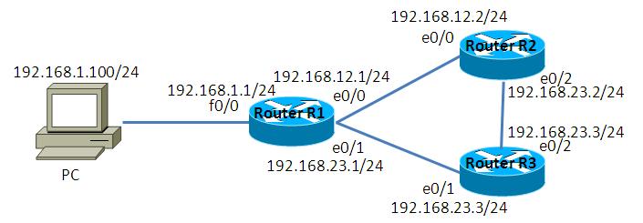
- netファイル
model = 3620
[localhost]

	[[3620]]
		image = C:\Program Files\Dynamips\images\c3620-j1s3-mz.123-18.bin
		ram = 128

	[[ROUTER R1]]
		f1/0 = NIO_gen_eth:\Device\NPF_{EEC4A317-FFD6-4B4A-9787-64BB3651D3B0}
		e0/0 = R2 e0/0
		e0/1 = R3 e0/1

	[[ROUTER R2]]
		e0/2 = R3 e0/2

	[[ROUTER R3]]
- 初期設定 R1
!
version 12.3
service timestamps debug datetime msec
service timestamps log datetime msec
no service password-encryption
!
hostname R1
!
boot-start-marker
boot-end-marker
!
!
no aaa new-model
ip subnet-zero
!
!
!
ip cef
!
!
!
!
!
!
!
!
!
!
!
!
!
!
!
interface Loopback0
 ip address 1.1.1.1 255.255.255.255
!
interface Ethernet0/0
 ip address 192.168.12.1 255.255.255.0
 half-duplex
!
interface Ethernet0/1
 ip address 192.168.13.1 255.255.255.0
 half-duplex
!
interface Ethernet0/2
 no ip address
 shutdown
 half-duplex
!
interface Ethernet0/3
 no ip address
 shutdown
 half-duplex
!
interface FastEthernet1/0
 ip address 192.168.1.1 255.255.255.0
 duplex auto
 speed auto
!
router eigrp 1
 passive-interface default
 no passive-interface Ethernet0/0
 no passive-interface Ethernet0/1
 network 1.1.1.1 0.0.0.0
 network 192.168.1.1 0.0.0.0
 network 192.168.12.1 0.0.0.0
 network 192.168.13.1 0.0.0.0
 no auto-summary
!
ip http server
ip classless
!
!
!
!
!
!
!
!
line con 0
line aux 0
line vty 0 4
!
!
end
- 初期設定 R2
!
version 12.3
service timestamps debug datetime msec
service timestamps log datetime msec
no service password-encryption
!
hostname R2
!
boot-start-marker
boot-end-marker
!
!
no aaa new-model
ip subnet-zero
!
!
!
ip cef
!
!
!
!
!
!
!
!
!
!
!
!
!
!
!
interface Loopback0
 ip address 2.2.2.2 255.255.255.255
!
interface Ethernet0/0
 ip address 192.168.12.2 255.255.255.0
 half-duplex
!
interface Ethernet0/1
 no ip address
 shutdown
 half-duplex
!
interface Ethernet0/2
 ip address 192.168.23.2 255.255.255.0
 half-duplex
!
interface Ethernet0/3
 no ip address
 shutdown
 half-duplex
!
router eigrp 1
 passive-interface default
 no passive-interface Ethernet0/0
 no passive-interface Ethernet0/2
 network 2.2.2.2 0.0.0.0
 network 192.168.12.2 0.0.0.0
 network 192.168.23.2 0.0.0.0
 no auto-summary
!
ip http server
ip classless
!
!
!
!
!
!
!
!
line con 0
line aux 0
line vty 0 4
!
!
end
- 初期設定 R3
!
version 12.3
service timestamps debug datetime msec
service timestamps log datetime msec
no service password-encryption
!
hostname R3
!
boot-start-marker
boot-end-marker
!
!
no aaa new-model
ip subnet-zero
!
!
!
ip cef
!
!
!
!
!
!
!
!
!
!
!
!
!
!
!
interface Loopback0
 ip address 3.3.3.3 255.255.255.255
!
interface Ethernet0/0
 no ip address
 shutdown
 half-duplex
!
interface Ethernet0/1
 ip address 192.168.13.3 255.255.255.0
 half-duplex
!
interface Ethernet0/2
 ip address 192.168.23.3 255.255.255.0
 half-duplex
!
interface Ethernet0/3
 no ip address
 shutdown
 half-duplex
!
router eigrp 1
 passive-interface default
 no passive-interface Ethernet0/1
 no passive-interface Ethernet0/2
 network 3.3.3.3 0.0.0.0
 network 192.168.13.3 0.0.0.0
 network 192.168.23.3 0.0.0.0
 no auto-summary
!
ip http server
ip classless
!
!
!
!
!
!
!
!
line con 0
line aux 0
line vty 0 4
!
!
end
検証1 検証環境構築
- PIMの設定
R1, R2, R3の各I/Fに対して、PIMを有効にします。
R1(config)#ip multicast-routing
R1(config)#
R1(config)#
R1(config)#interface Loopback 0
R1(config-if)#ip pim sparse-mode
R1(config-if)#
*Mar  1 00:17:28.259: %PIM-5-DRCHG: DR change from neighbor 0.0.0.0 to 1.1.1.1 on interface Loopback0 (vrf default)
R1(config-if)#exit
R1(config)#
R1(config)#
R1(config)#interface FastEthernet 1/0
R1(config-if)#ip pim sparse-mode
R1(config-if)#
*Mar  1 00:18:12.423: %PIM-5-DRCHG: DR change from neighbor 0.0.0.0 to 192.168.1.1 on interface FastEthernet1/0 (vrf default)
R1(config-if)#
R1(config-if)#exit
R1(config)#
R1(config)#
R1(config)#interface range Ethernet 0/0 - 1
R1(config-if-range)#ip pim sparse-mode
R1(config-if-range)#
*Mar  1 00:18:26.271: %PIM-5-DRCHG: DR change from neighbor 0.0.0.0 to 192.168.12.1 on interface Ethernet0/0 (vrf default)
*Mar  1 00:18:27.271: %PIM-5-DRCHG: DR change from neighbor 0.0.0.0 to 192.168.13.1 on interface Ethernet0/1 (vrf default)
R1(config-if-range)#

R2(config)#ip multicast-routing
R2(config)#
R2(config)#
R2(config)#interface Loopback 0
R2(config-if)#ip pim sparse-mode
R2(config-if)#
*Mar  1 00:20:17.935: %PIM-5-DRCHG: DR change from neighbor 0.0.0.0 to 2.2.2.2 on interface Loopback0 (vrf default)
R2(config-if)#exit
R2(config)#
R2(config)#
R2(config)#interface Ethernet 0/0
R2(config-if)#ip pim sparse-mode
R2(config-if)#
*Mar  1 00:20:27.155: %PIM-5-NBRCHG: neighbor 192.168.12.1 UP on interface Ethernet0/0 (vrf default)
*Mar  1 00:20:29.047: %PIM-5-DRCHG: DR change from neighbor 0.0.0.0 to 192.168.12.2 on interface Ethernet0/0 (vrf default)
R2(config-if)#exit
R2(config)#
R2(config)#
R2(config)#interface Ethernet 0/2
R2(config-if)#ip pim sparse-mode
R2(config-if)#
*Mar  1 00:20:44.603: %PIM-5-DRCHG: DR change from neighbor 0.0.0.0 to 192.168.23.2 on interface Ethernet0/2 (vrf default)
R2(config-if)#

R3(config)#ip multicast-routing
R3(config)#
R3(config)#
R3(config)#interface Loopback 0
R3(config-if)#ip pim sparse-mode
R3(config-if)#
*Mar  1 00:22:34.839: %PIM-5-DRCHG: DR change from neighbor 0.0.0.0 to 3.3.3.3 on interface Loopback0 (vrf default)
R3(config-if)#exit
R3(config)#
R3(config)#
R3(config)#interface range Ethernet 0/1 - 2
R3(config-if-range)#ip pim sparse-mode
R3(config-if-range)#
*Mar  1 00:22:50.219: %PIM-5-NBRCHG: neighbor 192.168.23.2 UP on interface Ethernet0/2 (vrf default)
*Mar  1 00:22:50.227: %PIM-5-NBRCHG: neighbor 192.168.13.1 UP on interface Ethernet0/1 (vrf default)
*Mar  1 00:22:51.107: %PIM-5-DRCHG: DR change from neighbor 0.0.0.0 to 192.168.13.3 on interface Ethernet0/1 (vrf default)
*Mar  1 00:22:52.107: %PIM-5-DRCHG: DR change from neighbor 0.0.0.0 to 192.168.23.3 on interface Ethernet0/2 (vrf default)
R3(config-if-range)#
- PIMの確認
各I/Fに対してPIMが設定されている事とPIM neighborが確立されている事を確認します。(R2, R3の出力結果については省略)
R1#show ip pim interface

Address          Interface                Ver/   Nbr    Query  DR     DR
                                          Mode   Count  Intvl  Prior
1.1.1.1          Loopback0                v2/S   0      30     1      1.1.1.1
192.168.1.1      FastEthernet1/0          v2/S   0      30     1      192.168.1.1
192.168.12.1     Ethernet0/0              v2/S   1      30     1      192.168.12.2
192.168.13.1     Ethernet0/1              v2/S   1      30     1      192.168.13.3
R1#
R1#
R1#show ip pim nei
R1#show ip pim neighbor
PIM Neighbor Table
Mode: B - Bidir Capable, DR - Designated Router, N - Default DR Priority,
      S - State Refresh Capable
Neighbor          Interface                Uptime/Expires    Ver   DR
Address                                                            Prio/Mode
192.168.12.2      Ethernet0/0              00:04:48/00:01:21 v2    1 / DR S
192.168.13.3      Ethernet0/1              00:02:34/00:01:38 v2    1 / DR S
R1#
検証2 bidirectional PIMの設定
- bidirectional PIMの有効化
各ルータでbidirectional PIMを有効にします
R1(config)#ip pim bidir-enable

R2(config)#ip pim bidir-enable

R3(config)#ip pim bidir-enable
- RPの設定
R1をBSR候補、R2をRP候補として設定します。
R1(config)#ip pim bsr-candidate Loopback 0

R2(config)#access-list 1 permit 239.1.1.1
R2(config)#
R2(config)#ip pim rp-candidate Loopback 0 group-list 1 bidir
- RPの確認
各ルータがRPを認識しているかどうかをshow ip pim rp mappingコマンドで確認します。また、bidirという表記からbidirectional PIMである事が確認できます。
R3#show ip pim rp mapping
PIM Group-to-RP Mappings

Group(s) 239.1.1.1/32
  RP 2.2.2.2 (?), v2, bidir <- bidirectional PIMである事ができます。
    Info source: 1.1.1.1 (?), via bootstrap, priority 0, holdtime 150
         Uptime: 00:00:18, expires: 00:02:25
R3#
- DFの確認
bidirectional PIMでは、RPまで最短経路となる点をリンク毎に選出します。この点をDF(designated Forwarder)と呼び、ディストリビューションツリーを構築するのに使用します。
DFは以下のコマンドで確認でき、「*」の表記があるのがDFです。
DFは以下のコマンドで確認でき、「*」の表記があるのがDFです。
R1#show ip pim interface df
* implies this system is the DF
Interface                RP                DF Winner        Metric     Uptime
Loopback0                2.2.2.2          *1.1.1.1          409600     00:05:24
FastEthernet1/0          2.2.2.2          *192.168.1.1      409600     00:05:24
Ethernet0/0              2.2.2.2           192.168.12.2     0          00:05:23
Ethernet0/1              2.2.2.2           192.168.13.3     409600     00:05:23
R1#

R2#show ip pim interface df
* implies this system is the DF
Interface                RP                DF Winner        Metric     Uptime
Loopback0                2.2.2.2          *2.2.2.2          0          00:07:31
Ethernet0/0              2.2.2.2          *192.168.12.2     0          00:07:31
Ethernet0/2              2.2.2.2          *192.168.23.2     0          00:07:31
R2#

R3#show ip pim interface df
* implies this system is the DF
Interface                RP                DF Winner        Metric     Uptime
Loopback0                2.2.2.2          *3.3.3.3          409600     00:07:12
Ethernet0/1              2.2.2.2          *192.168.13.3     409600     00:07:12
Ethernet0/2              2.2.2.2           192.168.23.2     0          00:07:12
R3#
検証3 ディストリビューションツリーの確認
- ルーティングの定義
コマンドプロンプトで以下の通り入力し、マルチキャストパケットがDynagen環境へ送信できるよう設定します。
Microsoft Windows XP [Version 5.1.2600]
(C) Copyright 1985-2001 Microsoft Corp.

C:\Documents and Settings\tmp>route add 224.0.0.0 mask 240.0.0.0 19
2.168.1.1

C:\Documents and Settings\tmp>
- マルチキャストグループへの参加
VLC Media Playerを用いて、239.1.1.1のマルチキャストグループに参加します。
- マルチキャストグループへの参加確認
マルチキャストグループに参加できているかどうかをR1のshowコマンドで確認します。
R1#show ip mroute 239.1.1.1
IP Multicast Routing Table
Flags: D - Dense, S - Sparse, B - Bidir Group, s - SSM Group, C - Connected,
       L - Local, P - Pruned, R - RP-bit set, F - Register flag,
       T - SPT-bit set, J - Join SPT, M - MSDP created entry,
       X - Proxy Join Timer Running, A - Candidate for MSDP Advertisement,
       U - URD, I - Received Source Specific Host Report,
       Z - Multicast Tunnel, z - MDT-data group sender,
       Y - Joined MDT-data group, y - Sending to MDT-data group
Outgoing interface flags: H - Hardware switched, A - Assert winner
 Timers: Uptime/Expires
 Interface state: Interface, Next-Hop or VCD, State/Mode

(*, 239.1.1.1), 00:06:12/00:02:14, RP 2.2.2.2, flags: BC
  Bidir-Upstream: Ethernet0/0, RPF nbr 192.168.12.2
  Outgoing interface list:
    FastEthernet1/0, Forward/Sparse, 00:06:12/00:02:14
    Ethernet0/0, Bidir-Upstream/Sparse, 00:06:12/00:00:00

R1#
- ping送信
コマンドプロンプトに以下の通り入力し、ホストから239.1.1.1へのpingを送信します。
C:\Documents and Settings\tmp>ping 239.1.1.1

Pinging 239.1.1.1 with 32 bytes of data:

Request timed out.
Request timed out.
Request timed out.
Request timed out.

Ping statistics for 239.1.1.1:
    Packets: Sent = 4, Received = 0, Lost = 4 (100% loss),

C:\Documents and Settings\tmp>
- ディストリビューションツリーの確認
pingの送信によって作成されたディストリビューションツリーを確認します。sparse-modeと異なり、送信元ツリーが作成させていない事が分かります。
R1#show ip mroute 239.1.1.1
IP Multicast Routing Table
Flags: D - Dense, S - Sparse, B - Bidir Group, s - SSM Group, C - Connected,
       L - Local, P - Pruned, R - RP-bit set, F - Register flag,
       T - SPT-bit set, J - Join SPT, M - MSDP created entry,
       X - Proxy Join Timer Running, A - Candidate for MSDP Advertisement,
       U - URD, I - Received Source Specific Host Report,
       Z - Multicast Tunnel, z - MDT-data group sender,
       Y - Joined MDT-data group, y - Sending to MDT-data group
Outgoing interface flags: H - Hardware switched, A - Assert winner
 Timers: Uptime/Expires
 Interface state: Interface, Next-Hop or VCD, State/Mode

(*, 239.1.1.1), 00:07:04/00:02:56, RP 2.2.2.2, flags: BC
  Bidir-Upstream: Ethernet0/0, RPF nbr 192.168.12.2
  Outgoing interface list:
    FastEthernet1/0, Forward/Sparse, 00:07:04/00:02:26
    Ethernet0/0, Bidir-Upstream/Sparse, 00:07:04/00:00:00

R1#

R2#show ip mroute 239.1.1.1
IP Multicast Routing Table
Flags: D - Dense, S - Sparse, B - Bidir Group, s - SSM Group, C - Connected,
       L - Local, P - Pruned, R - RP-bit set, F - Register flag,
       T - SPT-bit set, J - Join SPT, M - MSDP created entry,
       X - Proxy Join Timer Running, A - Candidate for MSDP Advertisement,
       U - URD, I - Received Source Specific Host Report,
       Z - Multicast Tunnel, z - MDT-data group sender,
       Y - Joined MDT-data group, y - Sending to MDT-data group
Outgoing interface flags: H - Hardware switched, A - Assert winner
 Timers: Uptime/Expires
 Interface state: Interface, Next-Hop or VCD, State/Mode

(*, 239.1.1.1), 00:07:10/00:03:13, RP 2.2.2.2, flags: B
  Bidir-Upstream: Null, RPF nbr 0.0.0.0
  Outgoing interface list:
    Ethernet0/0, Forward/Sparse, 00:07:10/00:03:13

R2#

R3#show ip mroute 239.1.1.1
Group 239.1.1.1 not found
R3#
添付ファイル
