DynagenでCCIEを目指す
Frame Relay Dynagenを使用した設定例
最終更新:
it_certification
-
view
1. 目的
- Dynamips/Dynagenの設定ファイルを用いたフレームリレースイッチの設定方法を確認します。
2. 構成
2.1. 設定概要
- Dynamips/Dynagenの設定ファイルを用いてフレームリレースイッチを作成します。
- 構成はトップページ/動作検証 ネットワーク系/Frame Relay on multipoint sub Interfaceと同じです。
2.2. 構成図
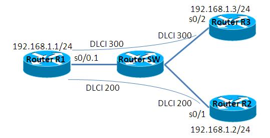
2.3. netファイル
model = 3620

[localhost]

    [[3620]]
        image = C:\Program Files\Dynamips\images\c3620-j1s3-mz.123-18.bin
        ram = 128

    [[FRSW SW]]
        1:200 = 2:200
        1:300 = 3:300

    [[ROUTER R1]]
        s0/0 = SW 1

    [[ROUTER R2]]
        s0/1 = SW 2

    [[router R3]]
        s0/2 = SW 3
2.4. 初期設定
- R1
デフォルト設定
- SW1
デフォルト設定
- R2
デフォルト設定
- R3
デフォルト設定
3. [検証] 設定投入
3.1. 物理I/Fの設定
R2, R3の物理I/Fに下記の設定を投入します。設定方法はルータをフレームリレースイッチとして代用した場合と、同様です。
Router(config)#hostname R2
R2(config)#
R2(config)#interface Serial 0/1
R2(config-if)#encapsulation frame-relay
R2(config-if)#ip address 192.168.1.2 255.255.255.0
R2(config-if)#no shutdown
R2(config-if)#^Z

Router(config)#hostname R3
R3(config)#
R3(config)#interface Serial 0/2
R3(config-if)#encapsulation frame-relay
R3(config-if)#ip address 192.168.1.3 255.255.255.0
R3(config-if)#no shutdown
R3(config-if)#^Z
ルータをフレームリレースイッチとして代用した場合と同様に、LMIによってDLCIが自動的に設定された事を確認します。
R2#show frame-relay pvc

PVC Statistics for interface Serial0/1 (Frame Relay DTE)

              Active     Inactive      Deleted       Static
  Local          0            0            0            0
  Switched       0            0            0            0
  Unused         1            0            0            0

DLCI = 200, DLCI USAGE = UNUSED, PVC STATUS = ACTIVE, INTERFACE = Serial0/1

  input pkts 0             output pkts 1            in bytes 0
  out bytes 34             dropped pkts 0           in pkts dropped 0
  out pkts dropped 0                out bytes dropped 0
  in FECN pkts 0           in BECN pkts 0           out FECN pkts 0
  out BECN pkts 0          in DE pkts 0             out DE pkts 0
  out bcast pkts 1         out bcast bytes 34
  5 minute input rate 0 bits/sec, 0 packets/sec
  5 minute output rate 0 bits/sec, 0 packets/sec
  pvc create time 00:01:25, last time pvc status changed 00:00:25
R2#

R3#show frame-relay pvc

PVC Statistics for interface Serial0/2 (Frame Relay DTE)

              Active     Inactive      Deleted       Static
  Local          0            0            0            0
  Switched       0            0            0            0
  Unused         1            0            0            0

DLCI = 300, DLCI USAGE = UNUSED, PVC STATUS = ACTIVE, INTERFACE = Serial0/2

  input pkts 0             output pkts 1            in bytes 0
  out bytes 34             dropped pkts 0           in pkts dropped 0
  out pkts dropped 0                out bytes dropped 0
  in FECN pkts 0           in BECN pkts 0           out FECN pkts 0
  out BECN pkts 0          in DE pkts 0             out DE pkts 0
  out bcast pkts 1         out bcast bytes 34
  5 minute input rate 0 bits/sec, 0 packets/sec
  5 minute output rate 0 bits/sec, 0 packets/sec
  pvc create time 00:01:34, last time pvc status changed 00:00:34
R3#
3.2. サブI/Fの設定
R1のサブI/Fに対して以下の設定を投入します。設定方法はルータをフレームリレースイッチとして代用した場合と、同様です。
R1(config)#interface Serial 0/0
R1(config-if)#encapsulation frame-relay
R1(config-if)#no ip address
R1(config-if)#no shutdown
R1(config-if)#exit
R1(config)#
R1(config)#interface Serial 0/0.1 multipoint
R1(config-subif)#frame-relay interface-dlci 200
R1(config-fr-dlci)#exit
R1(config-subif)#frame-relay interface-dlci 300
R1(config-fr-dlci)#^Z
3.3. 疎通確認
R1, R2, R3が疎通可能である事を確認します。
R1#ping 192.168.1.2

Type escape sequence to abort.
Sending 5, 100-byte ICMP Echos to 192.168.1.2, timeout is 2 seconds:
!!!!!
Success rate is 100 percent (5/5), round-trip min/avg/max = 8/16/36 ms
R1#
R1#
R1#ping 192.168.1.3

Type escape sequence to abort.
Sending 5, 100-byte ICMP Echos to 192.168.1.3, timeout is 2 seconds:
!!!!!
Success rate is 100 percent (5/5), round-trip min/avg/max = 8/32/100 ms
R1#
添付ファイル
