DynagenでCCIEを目指す
20100424 OSPF virtual-link 標準接続
最終更新:
it_certification
-
view
目的
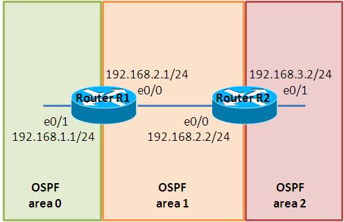
- virtual-linkによって、OSPF area 1とarea 2を接続する方法を確認します。
構成
- 設定概要
- OSPFによってルーティングします。
- 構成図
- netファイル
ghostios = True
sparsemem = True
model = 3620
[localhost]

	[[3620]]
		image = C:\Program Files\Dynamips\images\c3620-j1s3-mz.123-18.bin
		ram = 256

	[[ROUTER R1]]
		e0/0 = R2 e0/0

	[[ROUTER R2]]
- 初期設定 R1
!
version 12.3
service timestamps debug datetime msec
service timestamps log datetime msec
no service password-encryption
!
hostname R1
!
boot-start-marker
boot-end-marker
!
!
no aaa new-model
ip subnet-zero
!
!
!
ip cef
!
!
!
!
!
!
!
!
!
!
!
!
!
!
!
interface Loopback0
 ip address 1.1.1.1 255.255.255.255
!
interface Ethernet0/0
 ip address 192.168.2.1 255.255.255.0
 full-duplex
 no keepalive
!
interface Ethernet0/1
 ip address 192.168.1.1 255.255.255.0
 full-duplex
 no keepalive
!
interface Ethernet0/2
 no ip address
 shutdown
 half-duplex
!
interface Ethernet0/3
 no ip address
 shutdown
 half-duplex
!
router ospf 1
 log-adjacency-changes
 network 192.168.1.0 0.0.0.255 area 0
 network 192.168.2.0 0.0.0.255 area 1
!
ip http server
ip classless
!
!
!
!
!
!
!
!
line con 0
line aux 0
line vty 0 4
 login
!
!
end
- 初期設定 R2
!
version 12.3
service timestamps debug datetime msec
service timestamps log datetime msec
no service password-encryption
!
hostname R2
!
boot-start-marker
boot-end-marker
!
!
no aaa new-model
ip subnet-zero
!
!
!
ip cef
!
!
!
!
!
!
!
!
!
!
!
!
!
!
!
interface Loopback0
 ip address 2.2.2.2 255.255.255.255
!
interface Ethernet0/0
 ip address 192.168.2.2 255.255.255.0
 full-duplex
!
interface Ethernet0/1
 ip address 192.168.3.2 255.255.255.0
 full-duplex
 no keepalive
!
interface Ethernet0/2
 no ip address
 shutdown
 half-duplex
!
interface Ethernet0/3
 no ip address
 shutdown
 half-duplex
!
router ospf 1
 log-adjacency-changes
 network 192.168.2.0 0.0.0.255 area 1
 network 192.168.3.0 0.0.0.255 area 2
!
ip http server
ip classless
!
!
!
!
!
!
!
!
line con 0
line aux 0
line vty 0 4
 login
!
!
end
検証1 事前設定の確認
- ルーティングテーブルの確認
R1のルーティングテーブルを確認します。R1はarea 2の192.168.3.0/24への経路を知らない事が分かります。
R1#show ip route <- 192.168.3.0/24へのルートが見当たりません。
 - 略 -
     1.0.0.0/32 is subnetted, 1 subnets
C       1.1.1.1 is directly connected, Loopback0
C    192.168.1.0/24 is directly connected, Ethernet0/1
C    192.168.2.0/24 is directly connected, Ethernet0/0
検証2 virtual-linkの設定
- virtual-linkの設定
R1とR2の間をvirtual linkで接続します。R1に以下の設定を投入します。
R1(config)#router ospf 1
R1(config-router)#area 1 virtual-link 2.2.2.2
R1のみvirtual-linkが設定されている(R2は未設定)状態であると、以下のようなメッセージがR2に出力されます。
*Mar  1 00:07:43.095: %OSPF-4-ERRRCV: Received invalid packet: mismatch area ID, from backbone area must be virtual-link but not found from 192.168.2.1, Ethernet0/0
*Mar  1 00:07:53.051: %OSPF-4-ERRRCV: Received invalid packet: mismatch area ID, from backbone area must be virtual-link but not found from 192.168.2.1, Ethernet0/0
R2に以下の設定を投入します。
R2(config)#router ospf 1
R2(config-router)#area 1 virtual-link 1.1.1.1
- メッセージの確認
virtual-linkを介してneighborが確立されるとコンソール上に以下のメッセージが表示されます。R1に表示されるメッセージは以下の通りです。
*Mar 1 00:08:40.767: %OSPF-5-ADJCHG: Process 1, Nbr 2.2.2.2 on OSPF_VL0 from LOADING to FULL, Loading Done
R2に表示されるメッセージは以下の通りです。
*Mar 1 00:08:23.543: %OSPF-5-ADJCHG: Process 1, Nbr 1.1.1.1 on OSPF_VL0 from LOADING to FULL, Loading Done
- ルーティングテーブルの確認
R1のルーティングテーブルを確認すると、192.168.3.0/24が加わった事が確認できます。
R1#show ip route

     1.0.0.0/32 is subnetted, 1 subnets
C       1.1.1.1 is directly connected, Loopback0
C    192.168.1.0/24 is directly connected, Ethernet0/1
C    192.168.2.0/24 is directly connected, Ethernet0/0
O IA 192.168.3.0/24 [110/20] via 192.168.2.2, 00:01:21, Ethernet0/0 <- virtual-linkを介して伝わったルート
- virtual-linkの確認
show ip ospf virtual-linkでvirtual-linksを介したneighborが確立されているかを確認する事ができます。
R1#show ip ospf virtual-links
Virtual Link OSPF_VL0 to router 2.2.2.2 is up <- 設定が間違っている場合は、downとなっている事が多いです。
  Run as demand circuit
  DoNotAge LSA allowed.
  Transit area 1, via interface Ethernet0/0, Cost of using 10
  Transmit Delay is 1 sec, State POINT_TO_POINT,
  Timer intervals configured, Hello 10, Dead 40, Wait 40, Retransmit 5
    Hello due in 00:00:03
    Adjacency State FULL (Hello suppressed)                             <- neighbor間のステータスが確認できます。
    Index 1/2, retransmission queue length 0, number of retransmission 1
    First 0x0(0)/0x0(0) Next 0x0(0)/0x0(0)
    Last retransmission scan length is 1, maximum is 1
    Last retransmission scan time is 0 msec, maximum is 0 msec
R1#
show ip ospf interfaceでも同様の確認ができます。
R1#show ip ospf interface
OSPF_VL0 is up, line protocol is up
  Internet Address 192.168.2.1/24, Area 0
  Process ID 1, Router ID 1.1.1.1, Network Type VIRTUAL_LINK, Cost: 10
  Configured as demand circuit.
  Run as demand circuit.
  DoNotAge LSA allowed.
  Transmit Delay is 1 sec, State POINT_TO_POINT,
  Timer intervals configured, Hello 10, Dead 40, Wait 40, Retransmit 5
    oob-resync timeout 40
    Hello due in 00:00:00
  Index 2/3, flood queue length 0
  Next 0x0(0)/0x0(0)
  Last flood scan length is 1, maximum is 1
  Last flood scan time is 0 msec, maximum is 0 msec
  Neighbor Count is 1, Adjacent neighbor count is 1
    Adjacent with neighbor 2.2.2.2  (Hello suppressed)
  Suppress hello for 1 neighbor(s)
 - 略 -
添付ファイル
